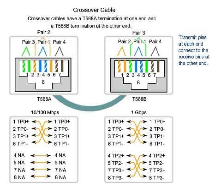
Is there a reason why the pin diagram of an RJ-45 looks like this?
I understand that the orange pair is used for Tx and the green pair for Rx. Why is it that the orange pair are kept together while the green pair are separated?
What are the consequences of messing around with this order as long as it is the same at both the ends?
123 Answers
From Wikipedia, emphasis mine:
Cables terminated in registered jack connectors used in building wiring and the telephone network normally consist of twisted pairs of wires. Wiring conventions were designed to take full advantage of the physical compatibility, thereby ensuring that using a smaller plug in a larger socket would pick up complete pairs, not a (relatively useless) two half pairs. But here again, there has been a problem.
The original concept was that the centre two pins would be one pair, the next two out the second pair, and so on until the outer pins of an eight-pin connector would be the fourth twisted pair. Additionally, signal shielding was optimized by alternating the live (hot) and earthy (ground) pins of each pair. This standard for the eight-pin connector is the USOC-defined pinout, but the outermost pair are then too far apart to meet the electrical requirements of high-speed LAN protocols.
Two variations known as T568A and T568B overcome this by using adjacent pairs of the outer four pins for the third and fourth pairs. [...]
So, the center pins 4 and 5, and their neighbours 3 and 6, follow the original conventions. But pins 2 and 7, and 1 and 8, could not follow that conventions due to electrical requirements. Hence the other two pairs are wired to pins 1 and 2, and 7 and 8.
Also note that keeping twisted pairs together is important to limit crosstalk. And different pairs have different twist rates, so maybe interchanging pairs (like using brown for blue, and blue for brown, on both sides of the cabling) affects electrical characteristics too; I'd stick to the standard colour scheme.
2General answer:
The actual reason for placement of specific signals in a connector, the design of the connector itself (and the color coding for the wires) is most likely hidden inside the technical standard(s) related to the connector and cabling.
For TECHNICAL reasons, e.g. avoiding "crosstalk", it is wise to place wiring that has signals with sharp edges (e.g. square wave) separate from signals that might get disturbed by the "noise" caused by the sharp transitions from "low" to "high" state of that OR make sure to have some type of shielding in between.
Reference:
"twisted pair" cabling (e.g. two intertwined wires) and also "balanced pair" exist as these help to mitigate trouble with disturbance (as above, and other).
Note:
"cross over"-type cables might not be needed, many network devices detect the correct polarity and adjust automatically.
my memory was that the 2 center pins were reserved for POTS so all computer network equipment was designed to utilize the outer 6 pins. Back when plain old telephones were still common there was a requirement that the RJ45 plugs be compatible with the plain old telephone and you could plug in a cord into the RJ45 jack and get a dialtone. Today however data networks utilize all 8 pins but to remain compatible with old networking gear we still keep with this standard.
The A/B difference is just to do with better performance. More modern and faster networking equipment requires you follow B wiring diagram as it offers better performance.